Operating Principles
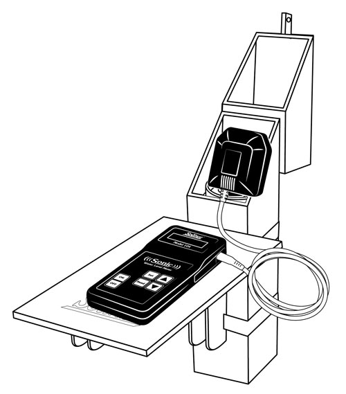
The Solinst Sonic Water Level Meter consists of a Control Unit and Probe. The Control Unit has a display, keypad, and comes with 6 AA alkaline batteries. The Probe contains a sound/pulse generator, microphone and temperature sensor.
The Sonic Water Level Meter works by the Probe transmitting a sound wave into the pipe, tube, or well and measuring the time it takes for the pulse to return after making contact with water. The depth to water is calculated using the speed of sound and time. Since the speed of sound varies with temperature, the temperature sensor located in the Probe adjusts for variations.
IMPORTANT
- The Sonic Water Level Meter Control Unit and Probe are not waterproof. They are resistant to rain or splashing, but can not be submerged.
Equipment Check and Setup
- Connect the Probe to the Control Unit by plugging the Probe cable connector into the connection on the side of the Control Unit. Ensure the connector is completely pushed in.
- Press the ON button. The Sonic WLM Version number should briefly display and then show "Depth* Searching". There should be a popping sound from the Probe, if not, ensure the Probe is plugged in properly. Turn the Sonic Water Level Meter OFF by pressing the button.
- Insert the Probe into the open well casing (less than 8" dia.), or drop tube, and then cover any open area around the Probe to stop the sound pulse from leaving the well. For example, use the plastic disc that is supplied with the Solinst Sonic Water Level Meter.
Notes:
- The seal around the probe does not need to be airtight, but the signal works better if there is a proper seal keeping the pulse inside the well. It also helps keep out external noise, including wind.
- If the top of the well or pipe is open, then it should be covered with a cap with a hole for the probe to access. The included plastic disc from Solinst is a good option.
- For highest accuracy, insert the Probe into open well casings less than 8" in diameter. Otherwise, use a 1/2" up to 2" diameter drop tube from top of well to just below the water level surface to avoid any disruptions to the sound pulse.
Water Level Measurement
- Press the ON button on the Control Unit. "Depth* Searching" will be displayed as it obtains a stable depth to water reading. The depth to water measurement will be displayed after a few seconds.
- To ensure the accuracy of the reading, use the Control Unit to enter specific well details such as drop tube diameter and the minimum and maximum water level measurement range. See the following sections for setting up these, and other parameters.
Note:
For the most accurate depth to water measurements, the water level measurement range minimum and maximum, and water temperature should be set.
- Press the ON button (or the Read button if already on). During or after "Depth* Searching" is displayed, press the down arrow to show the battery voltage.
Note:
Batteries should be replaced at 6.5 volts.
Setting Measurement Parameters
- Press the Set button repeatedly to scroll through the various settings (see page 2 for available set modes).
- Use the up and down arrow buttons to change a setting.
- When the desired setting is reached, press the Set button to save and advance to the next setting, or press Read to display the depth to water measurement.
Available Set Modes:
When the Set button is pressed, the Sonic WLM version number is displayed. Press the down arrow to read the Serial Number of the Sonic Water Level Meter.
WL Range Min (m/ft): Set the minimum range to start detecting. Setting a minimum range can also help ignore interferences at a specific depth. E.g. if the well casing ends at 10 m and your water level is below that at about 20 m, then the minimum range could be set to 15 m to ignore any reflection at 10 m. See "Well Obstruction" and "Depth to Water" considerations.
WL Range Max (m/ft): Set the maximum depth from which the Probe will listen for a returning pulse. If the approximate depth to water is known, don't set the Meter to listen for the returning pulse longer/deeper than required. A longer range gives less frequent returning pulses and increases the possibility of interference. A shorter range means more frequent pulses returning to the probe. See "Depth to Water" considerations.
In general, knowing the approximate water level before measuring allows you to set a minimum depth to start detecting, and a maximum depth to listen for the returning pulse. E.g. if depth to water is usually between 8–9 m, set your minimum to 7 m and your maximum to 10 m for higher accuracy.
Water Temp (ºC/ºF): Manually set the estimated temperature of the water inside your well. With the air temperature automatically detected by the sensor in the Probe, the two temperatures are used to calculate the speed of sound and therefore, the distance. Note: The distance error is small for variations in temperature, about 1% for a 10 ºF (5.6 ºC) temperature error.
Drop Tube Dia (cm/in): Set the drop tube diameter. This compensates for a reduced sound speed in tubes smaller than 5 cm (2") in diameter. The options for this setting are: >5 cm, 5 cm, 4.4 cm, 3.8 cm, 3.2 cm, 2.5 cm, 1.9 cm and 1.3 cm (>2", 2", 1.75", 1.5", 1.25", 1", 0.75", 0.5".
The following are the recommended maximum depths for each drop tube diameter: 1.3 cm to 120 m, 1.9 cm to 180 m, 2.5 cm to 300 m, 5 cm to 600 m (0.50" to 400 ft, 0.75" to 600 ft, 1" to 1,000 ft, 2" to 2,000 ft).
MP Offset (cm/in): Set the offset of the probe position from ground level – the zero point is the tip of the Probe. E.g. if the probe is inserted into a well cap that extends 75 cm above the ground. Then enter 75 cm for the offset. This will automatically be deducted from the depth reading. The value can be negative if the probe is installed on a casing below ground level.
Units: Select the measurement system for the data. The options are Metric for meters, centimeters, and degrees Celsius, or Eng ft for feet, inches, and degrees Fahrenheit.
Power Mode: Set in Normal or Power save mode. When in Normal mode there is an auto off after 15 minutes. When in Power save mode, there is an auto off after 3 minutes.
Contrast: Set the contrast level on the LCD screen from 0 (brightest) to 10 (dimmest).
Factory Reset: Sets the Control Unit back to the factory default configuration. Press the up button to make the selection. All settings will be set to the default values in Metric.


 German
 English